 Gareth and I are using ACS712 Low Current Sensors in our Aquaponics project. We’re using them to measure AC current. All we really need them to tell us is whether various pumps are on (and drawing 1/6 of an amp) or off.
The raw value you get when you do an analogRead on the pin varies between 0 and 1024. When there is no current flowing, ideally the value should be 512. When current is flowing, it should oscillate around 512 as its centre point.
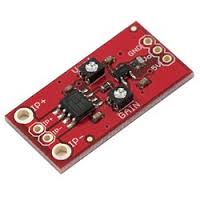
There are two pots on the ACS712 board – one for gain and one for offset. You can see them in this picture.
The offset pot should be set so that when no current is flowing, the raw reading is 512. The gain pot should be set so that when you apply the sort of current you want to measure, it varies considerably (remember we’re talking AC here) but doesn’t get too close to either extreme. Varying between 200 and 824 is a reasonable choice.
Hardware Calibration
For the hardware calibration stages, run a routine that outputs the raw value from the pin a few times a second. Three times is a good choice as 3 doesn’t go into 50Hz.
1. Set the offset pot
Turn off the current and fiddle with the offset pot until the reading is about 512. It varies a little even without the current being applied, so guesswork is involved.
Either there’s something about the ACS712 we don’t understand / are doing wrong, or the offset pot is vastly over-sensitive. Even with the gain set quite low, it jumps between 200 and 600 or so at the tiniest touch. I had to settle for an average of about 560 – I couldn’t get any closer. Turning up the gain at this stage would ideally make your setting more accurate, but in reality it doesn’t help.
2. Set the gain pot
Now, with the same routine running, apply a current (of the value you intend to measure) and start twiddling the gain pot until you see highs of around 800 and lows of around 200.
Software Calibration and Code
This is the code we are using to turn the oscillating values received from the ACS712 into an actual AC current reading:
float total = 0;
for (int i = 0; i < numberOfSamples; i++) {
float current = analogRead(pin) – 512;
total += current * current ;
}
value = abs(sqrt (total / numberOfSamples) – offset) * multiplier ;
The numberOfSamples variable is a class constant equal to 1000. The offset and multiplier are passed in by the calling code. We’re using three different sensors and they all need different ones, because it’s impossible to set the pots identically, but probably also due to differing lengths of wire.
The code works by adding up the squares of a thousand readings, then taking the root mean square. The multiplier is there to produce a reading in a real life unit – amps.
Because we couldn’t get rid of the offset in hardware, we have to compensate for it in software. I’m not convinced we’re doing it right; I can’t help thinking the offset should be taken off at the beginning, before all the squaring and averaging. But given that we’ve done it that way, here’s how to finish off the calibration.
1. Set the offset variable
At this point you need to run the code, rather than just output the raw readings. Start with your offset variable equal to 0 and your multiplier to 1, so that they have no effect.
Now turn off the current and watch the output. Set the offset variable to the number that gets it as close to zero as you can.
[Edit: It’s actually easier to do this if you remove the abs() from the code]
2. Set the multiplier variable
Now apply a known current. Find the multiplier that gives you a reading of that current.
If you have a better way to calibrate the ACS712, or better code to process the reading, please leave a comment and let us know!